
Introduction
Have you ever excitedly, perhaps a little inebriated, ordered a gadget off AliExpress, Shein, Temu, Amazon, etc.? One morning I woke up having ordered a pair of five watt LASER diodes. The legal limit for LASERs in Australia is one milliwatt! Thankfully I’d realised early enough and been able to cancel the order.
I had recently been looking into high frequency Tesla coils, otherwise known as plasma candles. So you’ll imagine my surprise when the postie drops a stereotypical AliExpress bag in the letterbox and, on opening it, I find a set of acrylic pieces to house one of the plasma candle kits I had been looking at. No Tesla coil, just the acrylic sheets. Oh well, I guess I know what my next purchase is!
So I purchased the remainder of the kit - the kit itself - and eagerly awaited its arrival. After about a week it arrived. Excitedly, I grabbed a knife and cut through the plastic bags, sliced open the cardboard box, and find several bags of components - there’s the primary, the secondary, reasonable MOSFET, nice heat sink and fan combo, … But no instructions. There is a slip of paper - perhaps it will have some online links - but no, it’s a series of instructions marked 1 - 4, but everything else is written in Chinese. I checked the comments and found lots of other people saying the same thing for plasma candle kits from lots of different vendors. So I guess I’m on my own.
And so it went. I found it relatively easy but not entirely clear. I think of myself as a pretty clever cookie, so if I struggled through it I thought others might like a set of instructions on completing the commonly-found “HFSSTC Plasma Candle” from Chinese markets such as AliExpress.
If you’re not using the acrylic case it is much faster to build - it should be obvious which instructions you need to follow and which you don’t. These instructions focus on building the acrylic frame and Tesla coil together.
Table of contents
<TODO>
Instructions
Preparation
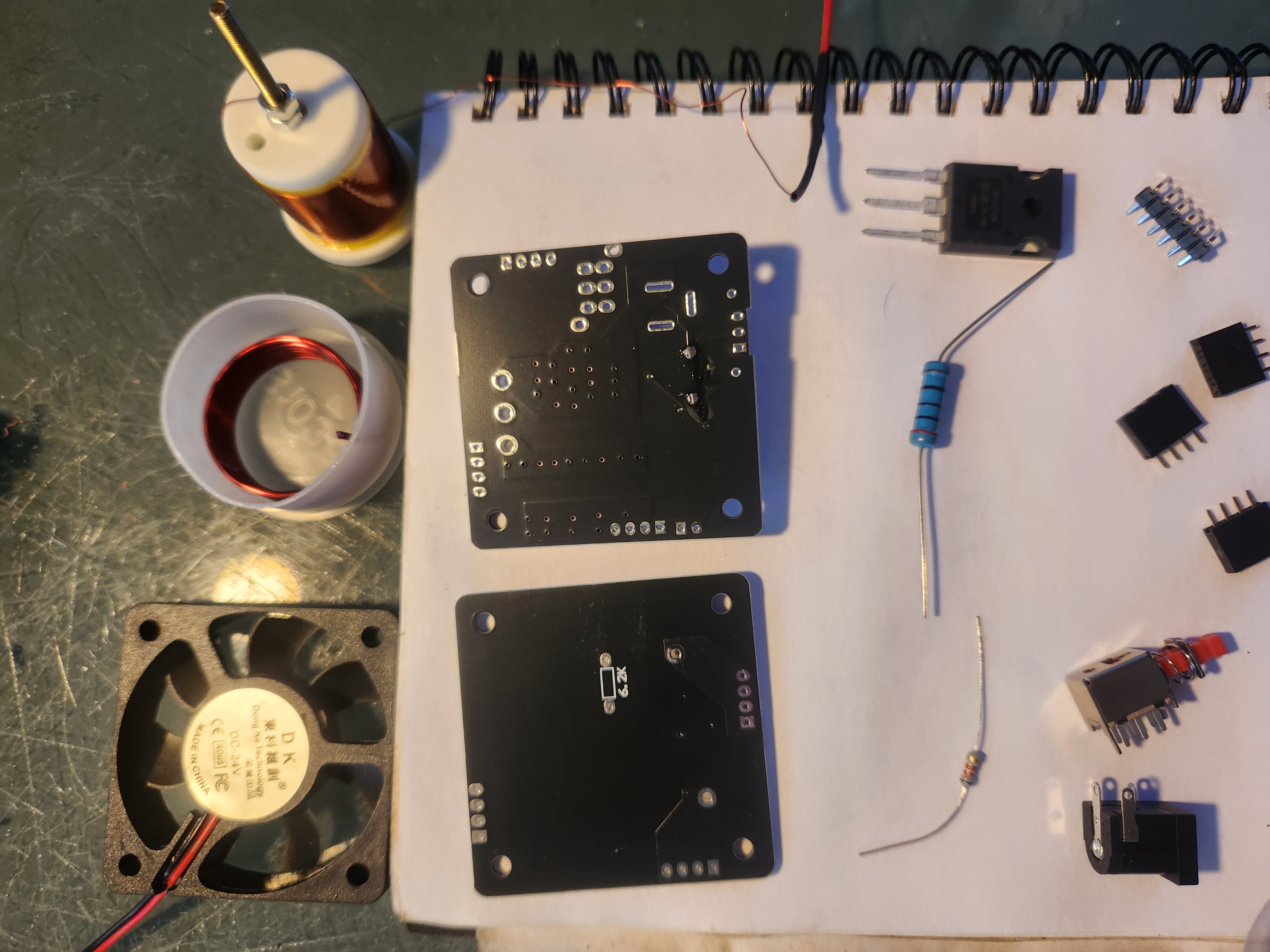
Don’t bother doing a parts count - they’ve supplied more than you need - but you do need to identify the different types of bolt. In the complete kit case (acrylic and Tesla coil) we have:
- Long silver bolts (at least 4)
- Long brass bolts (at least 4)
- Small silver bolts (at least 12)
- Even smaller silver bolts (at least 4)
- Small nuts (at least 20)
- Acrylic square with circular exhaust holes - This is the bottom of the case.
- Second acrylic square - the top
- Acrylic rectangle with both square and circle holes near its centre - these are for power supply and power button.
- Acrylic rectangle with a small rectangle cut out near its centre - This is for the pins that will stick out of the box and attach to the secondary coil for feedback. It will be opposite the above piece.
- Two more rectangular sides
- Two round pieces of acrylic, one with a small centre hole and the other being large enough to pass through the top (but not the bottom) of the secondary
- Two sets of four spacers, one set larger than the other
- Primary coil
- Secondary coil, with attached cable terminated with a black socket
- 200$\Omega$; 3 watt resistor - That’s the big one
- 6.2k$\Omega$; 350mW resistor - The little one
- MOSFET - The black thing with three legs
- Power cord adaptor
- On/Off switch
- Assorted pin headers
- Thermal paste
- Heat Sink
- 12V fan
- Assorted wires
- Primary coil PCB - This is the PCB with the round outline of the primary coil on it. We’ll be calling the side with the round outline the top side of the PCB.
- Driver PCB - This is the PCB that isn’t the Primary coil PCB. It doesn’t have an outline of the primary coil on it and does have a lot of pre-installed surface mount devices. We’ll call the top the side that has a Zener diode mounted in the air to keep it clear of other components.

Step 1
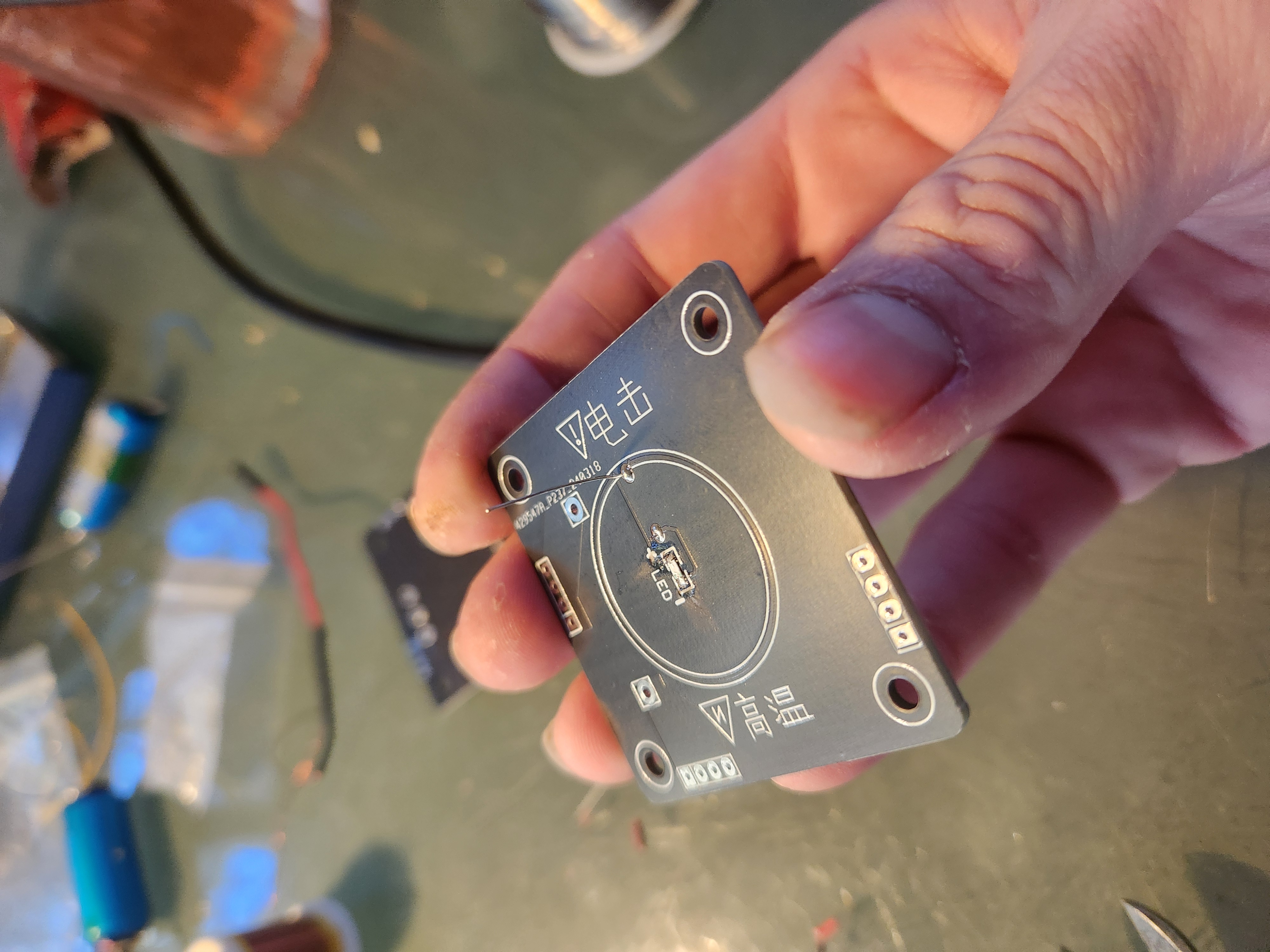
Take the Primary coil PCB - this is the PCB with the round outline of the primary coil on it. We’ll call the side with this outline the top.
Step 2
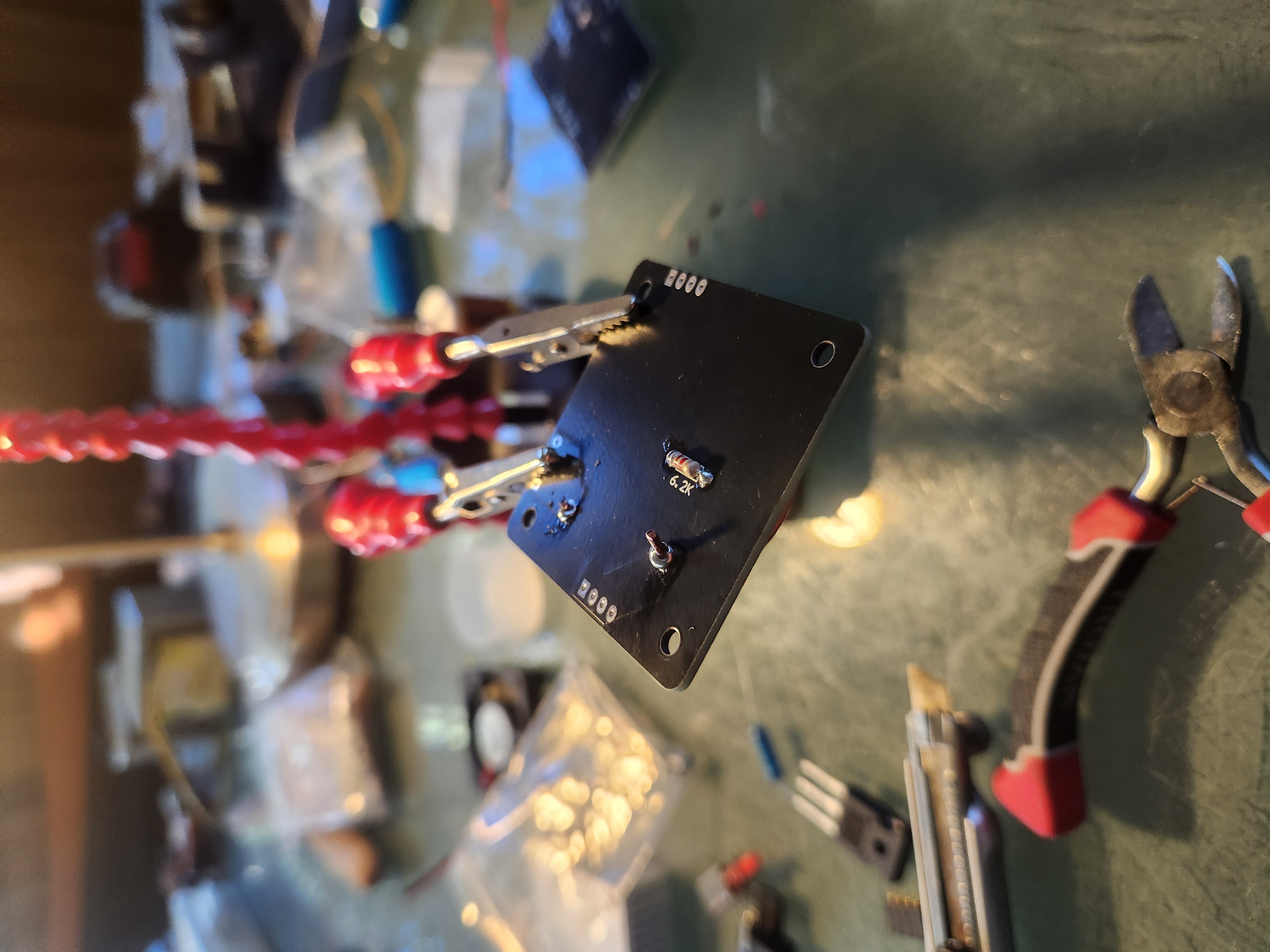
Solder the 6.2kΩ resistor (the small one) to the bottom of the primary coil’s PCB.

Step 3
Turn the PCB over and snip the legs from the resistor.
Step 4
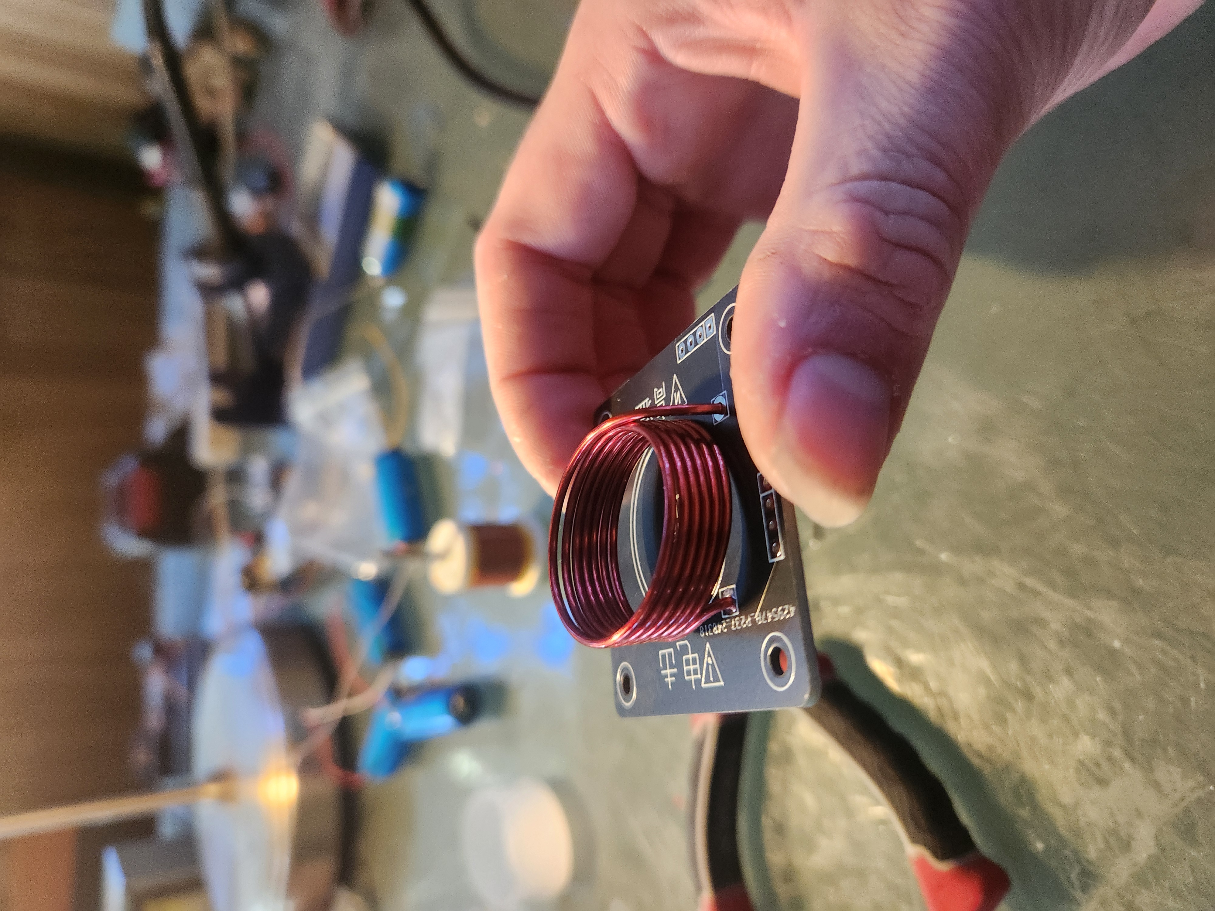
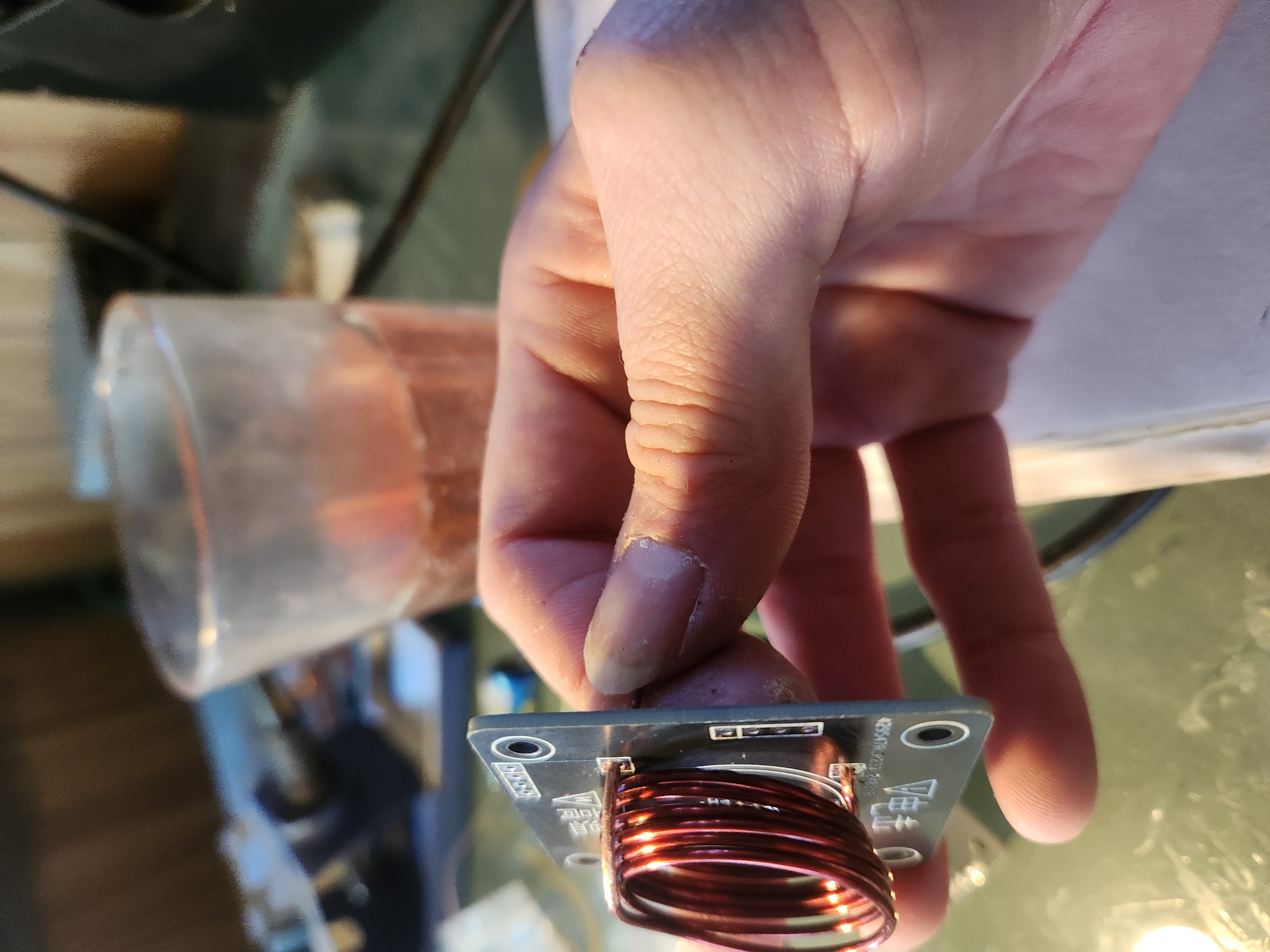
Take the primary coil - the small coil with relatively large wires - and shape it so that it fits reasonably into the holes on top of the primary PCB. It doesn’t need to be perfect, as long as it remains a coil without excessive horizontal or vertical gaps.
Step 5
Remove the primary coil and scrape or sand the enamel off the wire at the solder points. In my opinion it’s better to remove too much rather than too little enamel to ensure good solders.
Step 6
Solder the primary coil to the PCB. Using a multimeter test resistance at the solder points to confirm a good connection, then cut off any excess coil.
Step 7
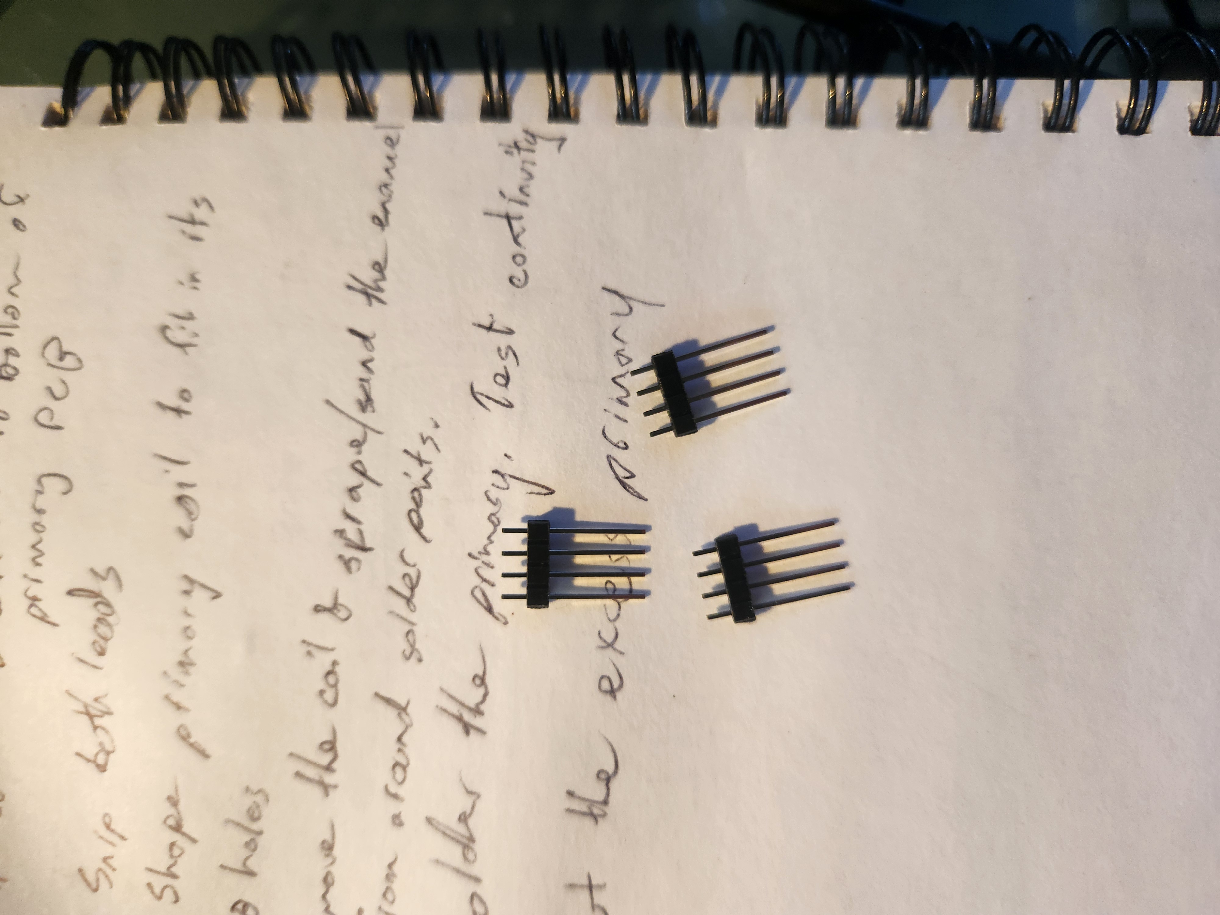
Take the straight pin headers; these are the ones that are mostly metal, with only a short “waist” off-centre. You’ll notice ridges between each pin, these are designed to simplify cutting to any length. Using a knife or fingernail make three pieces of four pin headers. See the attached picture if this isn’t clear.
Step 8
Attach these pin headers to the remaining spaces on the primary coil PCB, placing from below, with the longest legs on the ground, and soldering from the top. I often place pieces of blu-tack over the top of the pins that aren’t being soldered to prevent them falling out and to balance the PCB.
- The driver PCB has a few more components, I’d recommend starting with the power supply and power button. Add both to the PCB and solder. Test continuity using a multimeter - it’s easy to give too much solder to the switch and too little to the power socket.
- Gather the socket pin headers. These are the ones that are mostly black with a small length of metal sticking out to solder. We’ll need three sets of headers, each having four holes - the pins we soldered to the primary coil PCB will attach to the top of the driver PCB using these sockets.
- Insert the pins from below the driver PCB, so that a small length of metal appears on the top of the PCB for soldering. I find it easiest to insert all three pins and place a little blu-tack over the pins not currently being soldered to prevent them falling out and keep everything stable.
-
Next up the fan. Around the corner from from the power socket is a line of five holes - the outer two marked “200” and the inner three labelled “+ - +”.
Attach the red fan line to either positive (+) hole and the black line to the negative (-) hole. Be very conservative with the amount of solder you use, it’s easy to bridge solder pads on these small ones.
- Attach the 200Ω 3w resistor (the big one) to the points marked on the PCB - this resistor covers the fan connections so it’s important to complete step 12 first. Solder the resistor and trim the excess leads.
- Take the provided 90° pin headers and break off a connected pair (i.e. two pin headers in one piece). Find the last pair of holes on the PCB - it will be the side opposite the power supply and switch, near the left side when looking at the PCB, and solder them in place here, ensuring that the long legs are facing out; they will come through a hole in the acrylic wall.
-
The MOSFET attaches to the three remaining holes in the central area of the PCB, although its attachment in this kit takes a little thinking. The silver side (back) of the MOSFET needs to be in contact with the heat sink. This means inserting it from the bottom of the PCB and having it flipped so that, when bent over, its silver/back face will push against the heat sink.
Once you’re confident you have the MOSFET correctly aligned solder it in place and trim the leads if necessary.
- Carefully remove all covers on both sides of the acrylic
-
Take the bottom piece of acrylic - square with concentric circles - along with four large white spacers and four of the smallest screws. Be careful to get the smallest screws, not just the small ones.
Attach the spacers and screws to the bottom pieces and tighten to finger-tight.
-
Find the acrylic wall piece that has both a circle and square hole near the centre; attach this to the bottom piece so that the notches near the mid-height of the wall are below the circle and square holes.
To attach the side to the bottom, take one small bolt and nut. Push the nut halfway through the wider hole, slowly rotating the nut until you find the correct alignment. Insert the bolt to capture the nut. Twist anticlockwise a few times to ensure the threads are aligned then tighten finger-tight.
- Open the thermal paste and apply it liberally to the silver side of the MSOFET. From here on be careful not to rub in on too many things!
-
Place the fan inside the case, on top of the spacers. It is important that the screw plugs are facing down, and that the fan is rotated so that, when looking at the face containing the circle and square, the fan’s wires come out the right side of the case. Next, place the heat sink on top of the fan, fins facing the fan. Take four small white plastic spacers and place them in the corners, lined up with the heat sink’s screw holes. Finally, add the driver PCB to the stack. This should be rotated so that the large resistor is directly above the fan wires, and the button and power socket fit through their holes.
Take four of the longest screws and insert one in each corner. Take care of the position of the MOSFET - you want its entire body making contact with the heat sink - tighten the screws firmly (but not too firmly).
- Attach the primary coil PCB to the driver PCB by lining up the pins and sockets and inserting them firmly and completely.
- Assemble the remaining walls and secure them to both the bottom piece and their adjoining walls using nuts and bolts. The side opposite the first installed must use the side that has a rectangular hole around halfway along its length, and be flipped so that this hole is left of centre.
-
Take the remaining square piece of acrylic and attach it to the top (don’t add nuts and bolts yet!). The hole at 45° should be approximately inline with the rectangle containing the two 90° pins.
Take the circular piece of acrylic with the smallest centre hole and align the five holes with those on the top square.
Take the final acrylic circle and place it over the secondary. Place it on top of the stack and again align the five holes.
-
The wire at the end of the secondary has a black plug attached to it. Next to the exposed wire on one side of it is a small lever; use a fine knife or point to lever this up and remove the wire.
Poke the wire up through the notch, then down through the three holes at 45°. Keep poking until the wire comes out the tall rectangular hole above the hole containing the 90° pins.
Re-attach the black plug - if you used force detaching it you may need to push the lever back down so it catches the wire.
There’s a gap between the two circular acrylic pieces. I don’t know if it’s meant to be there, but it is. :)
-
Take four long brass bolts and slide them through the two circular pieces and top square, then remove the entire top section - three pieces of acrylic and secondary coil - and add nuts to the underside of each bolt, initially adding them loosely and then tightening only finger-tight.
Be carefull - because there is a gap between the circular pieces they can be cracked by over-tightening.
- Re-attach the top square to the case; secure it is place with nuts and bolts.
-
Finally, attach the wire from the secondary to one of the 90° pins. You may need to push the pins down from above if there isn’t enough clearance.
Tape down any loose copper wire at the end of the secondary winding to prevent it shorting to the winding.
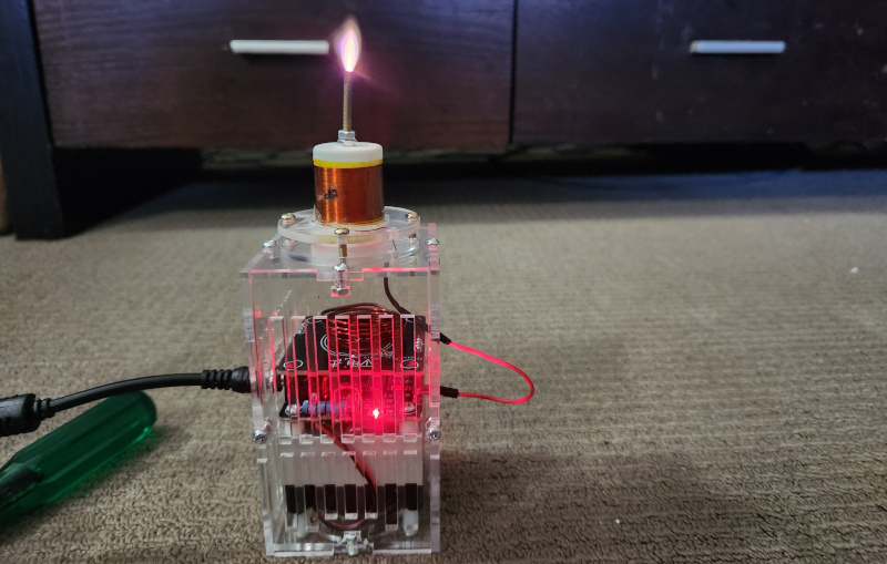
Plug it in and power it on! When warm it sometimes self-ignites, but you normally need to start it by touching the tip with something conductive - such as your finger.
A word of warning: The longer you leave it running - particularly if you give the arc a load to ground, the hotter the MOSFET will get. Pay attention to the heat blown out the sides of the heat sink’s fins and give it a chance to cool down when it begins to get hot, otherwise there’s a good chance the magic smoke will come out of the MOSFET and you’ll need to replace it.